Kuon Revox B77
Restoration Simulator
A Revox B77 reel-to-reel tape recorder you can turn, take apart and diagnose in the browser. Start from the symptom, land on the board and the part, read the expected voltage, and follow the procedure. Built from 29 circuit boards redrawn by Kuon R&D from the service manual (1,618 machine-checked connections), our restoration articles, and our verification guide. English first; German follows. No sign-up.
日本語の方へ。この道具は英語を軸に作っています(部品番号・信号名・測定点は整備マニュアルと同じ英語の表記で、国内外の部品商と照合できるためです)。走行系と音の模型は Kuon Revox B77 シミュレーター、日本語の修理記事は ジャーナル にあります。
Before you open the machine
- Unplug the mains cable. Not just the power switch: the switch, the fuse holder, the voltage selector and the primary of the transformer carry mains voltage whenever the plug is in.
- Discharge the reservoir capacitors on the power supply board (C1 2200 µF and C2 1000 µF) before touching or measuring anything. Confirm under 1 V with a meter. If you are in a hurry, use a 1 kΩ 5 W resistor across each; never a screwdriver.
- Oscilloscope ground goes to the 0.0 V terminal of the board you are measuring, never to the chassis, and never to the primary side. On the primary side use a differential probe or an isolation transformer or do not measure at all.
- A machine that has not been powered for years: bring the +21 V rail up slowly from a current-limited bench supply (0 to 21 V over about a minute, limit 100 mA) and watch the current. Replace any electrolytic that is bulging or leaking before you apply power.
- Take the reels off. A machine that starts unexpectedly will damage heads and tape.
- This is an unofficial educational tool by Kuon R&D. Revox is a trademark of Revox GmbH. Values marked calc are calculated from the redrawn schematics, values marked manual are quoted from the service manual, and nothing here has yet been confirmed on a running machine unless marked measured. You work at your own risk.
1 Your machine
The B77 was built in several versions. Choose yours and the tool shows which of the 29 board drawings apply, which capstan motor and timing capacitors you should find, and which parts are pending.
| Capstan shaft | 9.06 mm |
| Capstan motor | 1.021.320 |
| Speed control board | 1.177.325 |
| C8 / C9 | 1.6 nF / 4.7 nF |
| Tacho period at the higher speed | 625 µs |
| Oscillator | 1.177.243 |
| Heads (erase / record / reproduce) | 1.116.098.01 / 1.116.022.00 / 1.116.027.00 |
- Power supply 1.177.310 (or 311 / 312 by production run; read the number printed on your board)
- Tape drive control 1.177.317-81 (MKII): pending, not yet redrawn. 1.177.315 and 1.177.316 together describe the same functions
- Tape move sensor 1.177.321
- Capstan speed control 1.177.325-00 / -81 (MKII)
- Tape tension switch 1.177.135 / 136 / 137
- Audio interconnection 1.177.210-81
- Input amplifier 1.177.220 (CH I) and 1.177.221 (CH II, board 18)
- Record amplifier: 1.177.230 / 232 / 233 / 237 / 238 (boards 19 to 23) by equalisation and production run; read the number on your board
- Oscillator 1.177.240 (4-track) or 1.177.243 (2-track)
- Reproduce amplifier: 1.177.250 / 252 / 253 / 257 / 258 (boards 25 to 29); read the number on your board
- Monitor amplifier 1.177.260
2 The machine in 3D
Drag to turn, wheel to zoom, right-drag to move. Press a part to read what it is and where it leads. The explode slider takes the machine apart in the order you would on the bench: covers, reels, head block, pinch roller, then motors and boards out of the back. This is our own early MKI: black deck, aluminium band with the REVOX badge, transport buttons at the left, CHANNEL I and II meters at the right. Outer dimensions (452 × 414 × 207 mm, reels 538 mm across, reel centres 85 mm from the top) are from the dimension drawing in the service manual; the positions of the controls, heads, capstan and the parts inside come from our own front and rear photographs. Shapes are built from measurements, not scanned, so small parts are simplified; a photogrammetry scan of the machine will replace them one by one.
3 From the symptom to the part
Pick what the machine does. The causes are ordered the way we would check them: unplugged checks first (green), powered measurements second (red). Each cause names the board and the part, and the 3D button lights them up.
| State | Likely cause | Where | How to check | What to do |
|---|---|---|---|---|
| UNPLUGGED | Dried electrolytics on the speed control board | Board 11/12: C4, C5, C12, C13, C15, C18, C19 (C19 is tantalum, replace with electrolytic) | Visual: FRAKO gold cylinders, bulging tops. Measure ESR out of circuit if you can. | Replace all seven. This alone cures most unsteady speed. |
| MAINS ON | Speed trimmer R14 drifted or worn | Board 11/12, R14 10 k preset | Powered measurement. Acknowledge the safety notice at the top to show it. | Adjust R14; if it will not hold, replace with a multi-turn trimmer. |
| UNPLUGGED | Hardened or glazed pinch roller slipping on the capstan | Pinch roller 1.167.178.82 | Press the rubber with a fingernail: no give means hardened. Shiny band means glazing. | Replace the roller (procedure). Check pressure about 1.5 kg afterwards. |
| UNPLUGGED | Timing capacitors C8 and C9 off value | Board 11/12; values depend on machine type (1.6 nF and 4.7 nF for HS and STD) | Compare to the table on board 11 before touching them; they rarely drift (polystyrene and polycarbonate). | Replace only if speed cannot be stabilised, with 1 to 2 % parts of the table values. |
4 Procedures, one step at a time
Hardened or sticky rubber is the commonest cause of wow and flutter. Replacement is at the level of a plastic model kit if you respect the washers.
Unplug the mains cable. Lay the machine horizontal on a cloth so that nothing dropped is lost.
- UNPLUGGEDUnplug the mains cable. Lay the machine horizontal on a cloth so that nothing dropped is lost.
- UNPLUGGEDPull the control knobs upward; the power switch knob is stiff, lever it with two flat screwdrivers. Remove the lower panel screws (two, on some machines four, each with a washer) and lift the panel off its snap pins.
- UNPLUGGEDConfirm the machine is not in PLAY: the roller must be clear of the capstan.
- UNPLUGGEDPut a soft cloth under the arm. Remove the retainer (C clip or side bolt) from the groove of the roller shaft. Hold the groove at the top of the shaft with a flat screwdriver if it turns.
- UNPLUGGEDLift roller and shaft out together. Catch the thin plastic washers above and below the roller; they must go back in the same places.
- UNPLUGGEDClean the shaft and the sintered bronze bearing. If solvent touched the bearing, re-oil it lightly. Do not get oil on the new rubber; wipe with a little anhydrous ethanol only and let it dry.
- UNPLUGGEDLower washer on, new roller onto the shaft from the capstan side, upper washer, shaft fully home until the groove shows, retainer back in the groove. Check play and free rotation.
- UNPLUGGEDRefit the panel on its snap pins and screws, then the knobs.
- MAINS ONPowered measurement. Acknowledge the safety notice at the top to show it.
5 The 29 boards: parts, nets, notes
Every board redrawn from the service manual, with its parts list, the connections between them and the notes we wrote while drawing: what the board does, what to replace, and where the original was unclear. Press a part to see every net it sits on and the parts it shares them with. Three sheets are pending (1.177.317 MKI and MKII, 1.128.040) because the scan could not be read with certainty; we do not publish guesses.
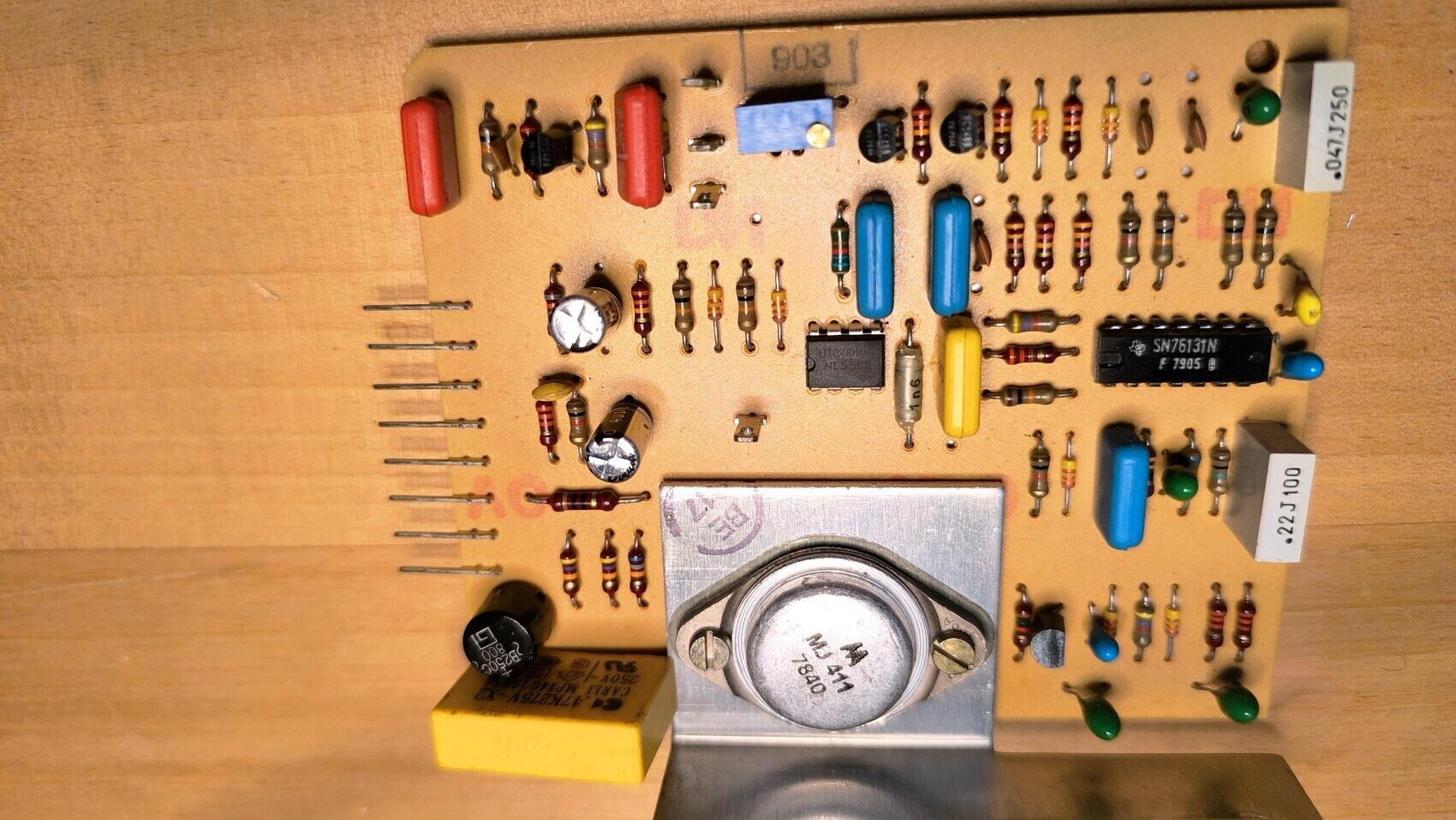
Loading board 11…
6 Capstan speed control on the bench
A numerical model of board 1.177.325 as drawn: tacho sine wave to square wave, divide by two at the slow speed, a fixed-width pulse from the NE555 for every edge, the average compared with a reference, and the difference driving the motor through the MJ411. Because the loop holds the pulse duty constant, the tacho period is proportional to the monostable width, and R14 moves that width. The 625 µs period is from the manual; how far R14 reaches, the motor time constant and how dried electrolytics reduce damping are this model's settings, not measurements.
- B Tacho input and amplifier (IC2A) (IC2, C22, R36, C23, R8, C3, R9)
- C Divide by two (Q3 / Q4) (Q3, Q4)
- D Speed select and trigger (Q1) (Q1)
- E Monostable IC1 (NE555), R14 sets pin 5 (IC1, R14, R15, C8, C9)
- F Error amplifier (IC2B) (IC2, R31, D6, C14, R29, C15)
- G Output stage (Q5, Q2 MJ411, bridge D1) (Q5, Q2, D1, R28, C13, R4, C1, R1, R2, C4)
7 Operating points, signal traces, modes
From our verification guide (Kuon R&D, 2026-08-27): the DC points the manual states, the ones we calculated from the drawings, and the order in which to follow a signal. Basis is marked on every value. Ground is always the 0.0 V terminal of the board, never the chassis.
| Board | Where | Expected | Basis | Condition | If it is off |
|---|---|---|---|---|---|
| +24.0 V, J5 pins 2, 11, 12 | Powered measurement. Acknowledge the safety notice at the top to show it. | calc | Rectified and smoothed only, not regulated | Much lower: D1 to D4 or C1 | |
| +21.0 V, J5 pins 13, 14 | Powered measurement. Acknowledge the safety notice at the top to show it. | calc | IC1 78M20 lifted by R1 1.8 k and R3 82 Ω: 20 × (1 + 82/1800) = 20.9 V plus IC current | Exactly 20.0 V: R3 open. Well above 21.4 V: R1 open | |
| +20.0 V, J3 pin 4 | Powered measurement. Acknowledge the safety notice at the top to show it. | calc | Series dropper, falls with load current | Large difference: the load side | |
| Ripple on +21.0 V | Powered measurement. Acknowledge the safety notice at the top to show it. | calc | Scope AC coupled, 20 mV/div | Large: C3 100 µF 3 V tantalum | |
| Ripple on +24.0 V | Powered measurement. Acknowledge the safety notice at the top to show it. | calc | Normal before regulation | Several volts: C1 lost capacitance | |
| +21.0 V | Powered measurement. Acknowledge the safety notice at the top to show it. | calc | Board 1.177.312 uses an LM317; the 78M20 figures do not apply | ||
| Q1 collector | Powered measurement. Acknowledge the safety notice at the top to show it. | manual | RECORD, S-OSC at +24 V. Rises slowly through C3 220 µF and R5 | ||
| T1 pin 8 | Powered measurement. Acknowledge the safety notice at the top to show it. | manual | RECORD, scope with ×10 probe | ||
| Erase head | Powered measurement. Acknowledge the safety notice at the top to show it. | manual | RECORD | ||
| Record head cold side (0-REC) | Powered measurement. Acknowledge the safety notice at the top to show it. | manual | RECORD | ||
| Y-LINE, J17 pins 10, 11 | Powered measurement. Acknowledge the safety notice at the top to show it. | manual | Reference level signal applied | ||
| Q8, Q10 collectors | Powered measurement. Acknowledge the safety notice at the top to show it. | manual | Reference level signal applied | ||
| IC1, IC2 pin 3 | Powered measurement. Acknowledge the safety notice at the top to show it. | manual | No signal. Midpoint of R11 and R14 (10 k / 10 k), half of +21 V | ||
| Output of C4, C10 | Powered measurement. Acknowledge the safety notice at the top to show it. | manual | Headphone side | ||
| Q4 emitter | Powered measurement. Acknowledge the safety notice at the top to show it. | manual | Relay circuit, +21 V through R23 4.7 k | ||
| +21D at the C21 side of R45 | Powered measurement. Acknowledge the safety notice at the top to show it. | calc | R45 1 k carrying about 2.2 mA for two head amplifier stages. If it reads exactly 21 V, our reading of R45 as a supply filter is wrong; tell us | ||
| Q4 collector | Powered measurement. Acknowledge the safety notice at the top to show it. | manual | The original notes +12 V here, through R16 12 k | ||
| IC1 pins 3 and 5 | Powered measurement. Acknowledge the safety notice at the top to show it. | calc | Midpoints of R18/R15 and R21/R24 (220 k / 220 k) | ||
| Pin 8 (point A), ground on P5 | Powered measurement. Acknowledge the safety notice at the top to show it. | manual | 1.177.325. Board 1.177.326: 833 µs, 2.5 Vpp. Board 1.177.327: 1666 µs, 3 Vpp | Adjust R14; if unstable, the electrolytics first |
- Powered measurement. Acknowledge the safety notice at the top to show it.
- Powered measurement. Acknowledge the safety notice at the top to show it.
- Powered measurement. Acknowledge the safety notice at the top to show it.
- Powered measurement. Acknowledge the safety notice at the top to show it.
- Powered measurement. Acknowledge the safety notice at the top to show it.
- Powered measurement. Acknowledge the safety notice at the top to show it.
- Powered measurement. Acknowledge the safety notice at the top to show it.
- Powered measurement. Acknowledge the safety notice at the top to show it.
- Powered measurement. Acknowledge the safety notice at the top to show it.
- Powered measurement. Acknowledge the safety notice at the top to show it.
- Powered measurement. Acknowledge the safety notice at the top to show it.
- Powered measurement. Acknowledge the safety notice at the top to show it.
- Powered measurement. Acknowledge the safety notice at the top to show it.
- Powered measurement. Acknowledge the safety notice at the top to show it.
- Powered measurement. Acknowledge the safety notice at the top to show it.
- Powered measurement. Acknowledge the safety notice at the top to show it.
- Powered measurement. Acknowledge the safety notice at the top to show it.
| Mode | Pinch roller | Brakes | Left motor | Right motor | Audio | REC |
|---|---|---|---|---|---|---|
| POWER ON | off | locked | stop | stop | mute | off |
| PLAY | on | free | weak reverse (back tension) | strong forward (take-up) | output | off |
| PLAY + REC | on | free | weak reverse | strong forward | output | on |
| STOP | off | locked | stop | stop | mute | off |
| FORW | off | free | weak forward (assist) | strongest forward | mute | off |
| REW | off | free | strongest reverse | weak reverse (assist) | mute | off |
| PAUSE | off | locked | stop | stop | mute | on when recording |
| Tape end | off | locked | stop | stop | mute | off |
8 Open data and how to help
We want this to become a resource that B77 owners complete together. The board data behind this page is published as JSON and may be used under CC BY 4.0 with attribution to Kuon R&D; our photographs are free to reproduce with credit. Nothing here is affiliated with Revox GmbH.
- Board data: index.json and
/analog-tools/revox-b77/data/boards/NN.json(parts, nets, notes per board, generated from the KiCad drawings). - Pending: tape drive control 1.177.317 (MKI) and 1.177.317-81 (MKII), remote control unit 1.128.040. A sharp photograph of either board or a cleaner scan of those pages lets us finish them.
- Not yet confirmed on a running machine: every value marked calc. If you measure one, tell us the board, the part or pin, our value, your value and the condition. Photographs help.
- What we will add next: the 29 schematic PDFs for download, a photogrammetry scan of our own machine replacing the parametric 3D parts, and German.
- Corrections and measurements: contact Kuon R&D. Sources: our articles on the transport, the boards, speed and calibration and the parts reference.